Construction of the Bali Sewage Treatment Plant was established by the former Pro-vincial Office of Housing and Urban Development (in 3 phases) based on the Provin-cial “Taipei Suburb Sewerage Systems Planning Report of June 1984.” Phase-1 con-struction started in 1987 and concluded in 1994; the Plant was inaugurated in June 1997 for user connection.
The Operation Management of Bali Sewage Treatment Plant was implemented based on the 1991.11.5 decision made by The Executive Yuan’s Public Construction Supervision Task Force: “Sewerage Systems in the Tamsui River System will be en-trusted to a dedicated management unit established by Taipei City Government; that in the provincial portion will be entrusted to Taipei City Government.” From June 1997 until now, the Sewerage Systems Office of the Public Works Department of Taipei City Government has the custody of sewerage systems as entrusted by The Executive Yuan. The Sewage Treatment Capacity of the Phase 1 construction is 132CMD, which in-cludes sewage excesses from New Taipei City, Keelung City and Taipei City; the post-treatment sewage is dispersed to Taiwan Straits through a 6,660m ocean outfall pipeline.
- Plant Address: No. 90, Museum Rd., Bali Dist., New Taipei City
- Tel: (02)2619-1987
- Fax: (02)2619-2004
Sewage Treatment Procedures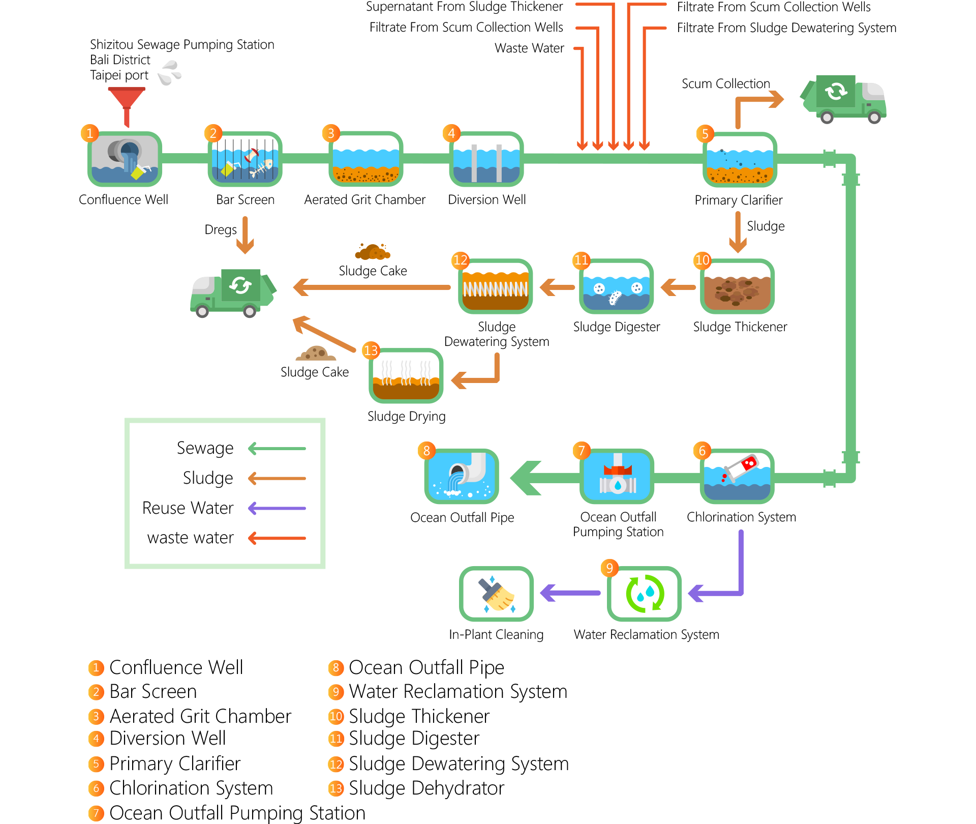
- After sewage enters the treatment plant, it first passes through a mechanical bar screen to remove large solid objects. Then it goes through an aeration and sedimentation tank to settle out sand and gravel, before entering a primary sedimentation tank to remove suspended solids.
- Sewage after sedimentation, except for a small portion used for internal plant water in the recycled water system, flows to the effluent junction of the marine outfall unit. It undergoes emergency chlorination by a chlorine addition system and is then pumped into the deaeration tower. After dilution and diffusion through the marine outfall pipe, it is discharged into the outer Taiwan Strait.
- After settling in the primary sedimentation tank, suspended solids are removed. The sludge is pumped by a sludge pump to a sludge mixing tank, and after concentration in a gravity thickening unit, it is transported to an egg-shaped anaerobic digestion unit for digestion treatment, and finally sent to a sludge digestion storage tank.
- The sludge undergoes dewatering in a sludge dewatering unit. The dewatered sludge is then transported to a sludge drying unit, dried, and subsequently transported to a waste treatment plant for further processing.
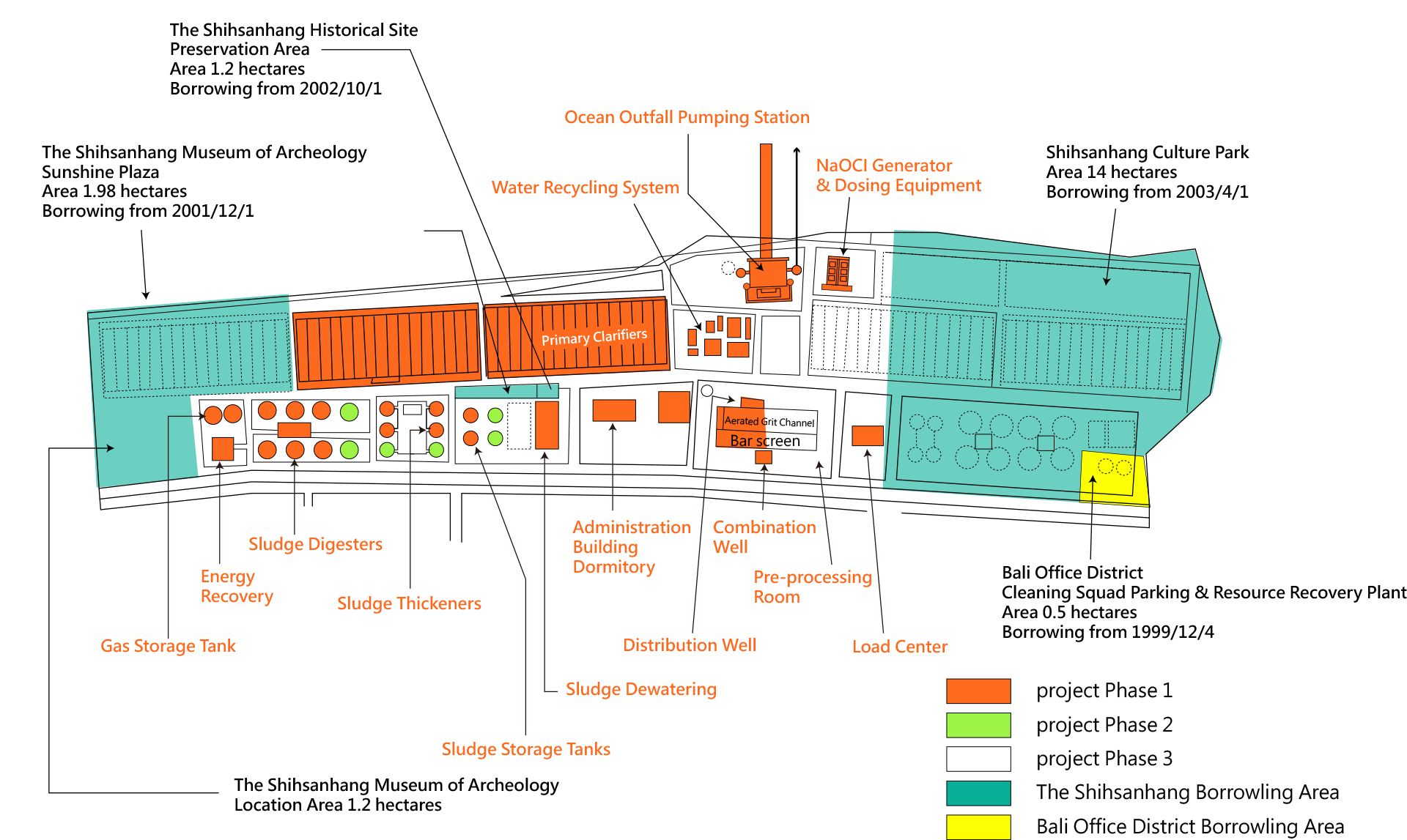
Facility Floorplan
 Main Facilities List
| Item | Name of Facility | Quantity | Dimensions |
|---|
| 1 | Management Building | 1 | L 53m, W 24.5m, above ground H 18.4m Description:- 4 levels Above Ground, 1 level underground
|
| 2 | Confluent Well | 1 | L 20m, W 15m, D 6.1m Description:- Hydraulic Retention Time 15.03s
- Average depth 2.42m
|
| 3 | Mechanical Bar Screen | 4 | Dimensions:W×D=3m×6m, pitch=12.5mm Description: |
| 4 | Aerated Grit Chamber | 8 | Dimensions:L 27m, W 6m, D 8.2m Description:- Hydraulic Retention Time 5.73min.
- Average Depth 4.07m
- Each chamber comprises sand collector, spiral conveyer, spiral dehydrator, belt con-veyer
|
| 5 | Diversion Well | 1 | Dimensions:L 31m, W 10m, D 8.5m Description:- Hydraulic Retention Time 1.8min.
- Average Depth 5.45m
|
| 6 | Primary Clarifier | 32 | Dimensions:L 72m, W 13.8m, D4.2m Description:- Hydraulic Retention Time 1.97hrs
- Average Depth 3.5m
- Surface overflow rate 42.6 CMD/㎡
- Each with horizontal and vertical scraper, sludge collector
|
| 7 | Ocean Out-fall Pumping Station | 1 | Dimensions:L 54m, W 40m, H 22m Description:- Pump x4; Axical flow, Q = 7.66 CMS, 327 rpm, TDH = 31.5M Power output = 3 phase 6600V, 2500hp
|
| 8 | Sludge Mix-ing Tank | 1 | Dimensions:Dia. 10m, H 9m Description:- Hydraulic Retention Time 34.6min.
- Average Depth 7m
- With stirrer x1, sludge intake pump x6
|
| 9 | Sludge Thickener | 4 | Dimensions:Dia. 21m, H 9m Description:- Hydraulic Retention Time 8hrs
- Average Depth 5.5m
- With Stirrer x4, Sludge delivery pump x4
|
| 10 | Supernatant Storage Tank | 1 | Dimensions:Dim. 10m, H 9m Description:- Hydraulic Retention Time 0.4hrs
- Average Depth 5m
- With stirrer x1, Supernatant delivery pump x4
|
| 11 | Sludge Thickener Tank | 1 | Dimensions:Dia. 5m, H 9m Description:- Hydraulic Retention Time 0.8hrs
- Average Depth 6m
- With stirrer x1, sludge digest intake pump x4
|
| 12 | Egg-shaped Digester | 6 | Dimensions:Dia. 24.35m, H 40m Description:- Digest days: 18
- Gas production: 3700m3/h/tank
- Volume of egg-shaped digester 9000m3
|
| 13 | Sludge Di-gest Tank | 2 | Dimensions:Dia. 20m, H 5.52m Description:- Retention Time 13.52hrs
- Average Depth 4m
- With stirrer x2; dehydrated sludge intake pump x8
|
| 14 | Digest Ma-chine Room | 1 | Dimensions:L 44m, W 21m, above ground H 7m, un-derground D 6m Description:- With Digest Sludge Intake System, Scum System, hot-water system
|
| 15 | Energy Re-cycle Ma-chine Room | 1 | Dimensions:L 33m, W 27.6m, above ground H 10m,underground D 5m Description:- Include water supply system, compressed air system, desulfurization system, gas col-lection system
|
| 16 | Dual fuel en-gine | 4 | Description:- Dual fuel engine, capable of power recycle 5300kW/day, heat recycle 5000kW/day
|
| 17 | Sludge De-hydrator Machine Room | 1 | Dimensions:L 65m, W 20m, H 9m Description:- Dehydrator x7; Sludge intake=20.00m3/h, Solid load = 1.00kg.DS/h; solid recycle rate = 95%; power output = 3-ph, 460V, 5hp; filter fabric width 2.6m
- Average Sludge Treatment 3027m3/day
- Solid content in sludge cake: 25%
- Weight of sludge cake: 38.5t/day
|
| 18 | Seawater Electrolysis and Chlorina-tion System | 1 | Dimensions:Seawater Electrolysis and Chlorination ma-chine room L 47.2m, W 39.4m, H 7.2m; Seawater Pumping Well Dia. 7m, H 10m; Chlorination Model Pool L16.3m, W2.6m, D 1.15m。 Description:- With seawater pump x3, circulation pump x12, electrolysis tank x6, sodium hypo-chlorite intake pump x6
- The equipment is currently not in use
|
| 19 | Water Recy-cle System | 1 | Dimensions:Coagulation-sedimentation Pool Dia. 6.74m, D 7.1m; recycle water temporary storage L 15m, W 10m, D 4.5m; sludge temporary storage L 12m, W 6m, D 2.8m; sludge de-livery pool L 6m, W 6m, D 2.8m; Backwash wastewater tank L 3m, W 2.55m, D 5.45m Description:- With recycle water pump station, fine sieve machine room, recycle water coagula-tion-sedimentation pool, temporary storage, sludge temporary storage, sludge delivery pool, recycle water storage, backwash wastewater tank, effluent pump station
- Treatment Volume 6000m3/D
- Fine Sieve x3, Q = 500 m^3/hr; D*L = 3M*4.5 M; power output = 3-ph, 460V, 7.5HP
|
| 20 | Ocean Out-fall Pipe | 1 | Dimensions:Dia. 3.6m; L 6,660m Description: |


![Taiwan.gov.tw [ open a new window]](/images/egov.png)